


Conclusion first
TTL-to-serial usually converts electrical conditions
A development board has TXD and RXD, while an instrument has RS232 or RS485; you cannot just connect the wires together. The UART on the board is already a serial transmit/receive circuit. So-called TTL-to-serial usually means adapting logic levels to another type of serial line. The byte content may not change, but voltage, reference method, and drive capability must match.
TTL originally referred to a logic circuit technology. In module names, TTL serial often broadly means a board-level logic-level interface, and the actual devices may be CMOS. Do not assume from the name alone that it is necessarily 5 V, that all inputs tolerate 5 V, or that it can program any microcontroller. First check the supply, input/output ranges, and specific purpose.
How UART sends one byte over time
UART arranges data into a start bit, data bits, an optional parity bit, and stop bit(s). The receiver re-identifies the byte according to the corresponding format and rate. Asynchronous means no separate synchronization clock is sent, not that the two sides may freely use different baud rates. If baud rate, format, and flow control do not match, the wiring may be correct but the data can still be garbled.
For example, 9600 bit/s, 8N1 uses one start bit, eight data bits, and one stop bit, for a total of ten bit times. Sending one character continuously takes about 1.04 ms. This is a teaching calculation; it does not yet include application waiting, direction switching, or retries, and cannot be taken as an actual throughput guarantee for any module.
Check voltage and reference, and protect board-level inputs first
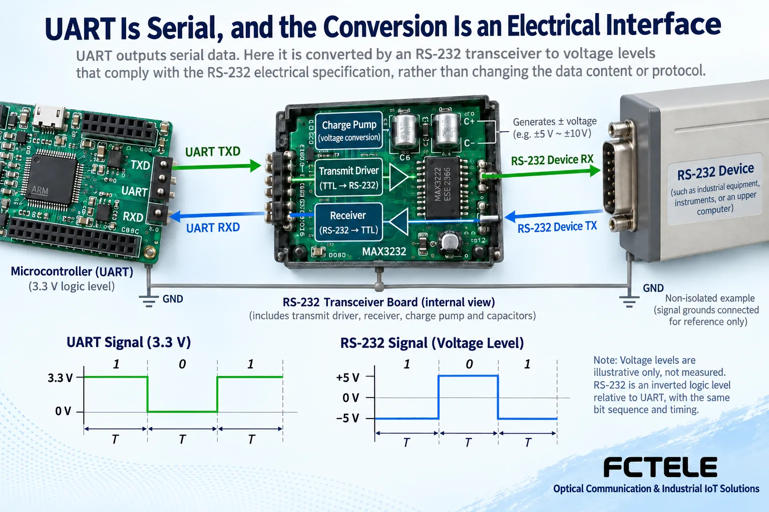
Whether a 3.3 V output can drive the other side depends on the receiver threshold; whether a 5 V output can be connected also depends on the allowed input and absolute maximum ratings. A module using a 3.3 V supply does not prove that all pins tolerate 5 V. RS232 line voltages also cannot be directly connected to ordinary UART inputs; they may be misread or even damage the device.
In an ordinary non-isolated connection, connect one end’s TXD to the other end’s RXD and establish a suitable signal reference. The two outputs must not be hard-connected together. VCC is power, not data. When both ends are already powered separately, do not connect their power supplies to each other without confirmation. For isolated two sides, the reference is handled separately according to the design; do not bypass the isolation barrier just to create a common ground.
Why RS232 transceivers have a charge pump and two directions
In common UART logic, a logic one corresponds to a high level, while on RS232 data lines a logic one corresponds to a negative voltage and a logic zero to a positive voltage. The transmit driver performs the electrical conversion, and the receiver restores board-level logic in the other direction. They preserve the corresponding information; you cannot say the byte order changed just because the waveform voltage polarity is reversed.
The TI MAX3232 document explains the division of labor among the driver, receiver, and charge pump. The charge pump works with capacitors to produce the required voltage conditions. The chip’s supply, load, and protection should be checked against the datasheet. This general principle does not prove that any unknown module uses the same device, and even less does it prove that the complete product has the same protection rating.
RS485 also has to handle who can transmit, in addition to differential signaling
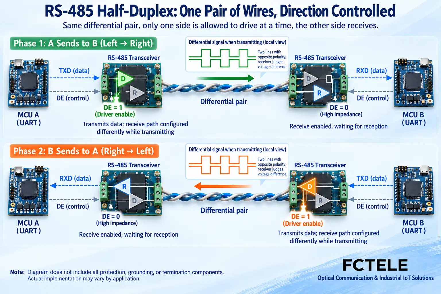
An RS485 receiver mainly looks at the voltage difference across the wire pair, and the transmit driver establishes the corresponding differential state. A differential pair can help suppress common-mode coupled interference, but the cable, termination, biasing, reference range, and protection still need to be designed. Two-wire half-duplex usually lets multiple nodes share the wire pair, and at any one moment only the appropriate driver should transmit.
The driver enable DE determines whether the transmitter occupies the line; receiver enable is a separate matter. Release after sending the complete character; too early may truncate it, and too late may block the reply. Automatic control also has applicable conditions. The A/B definitions in different documents should be checked by function; do not assume that cross-vendor polarity is consistent just because the letters are the same.
Changing only the transceiver cannot change the protocol or absorb unlimited speed differences
The electrical layer determines how the line represents states, the character format determines how bytes are formed, and the protocol determines what the bytes mean as commands. When two devices use different commands, correct voltage levels will not let them understand each other. If you want to change the rate, format, or protocol, you need corresponding processing and software capability; a single line driver is not enough.
A design with buffering can briefly absorb bursts, but if input continues faster than output, data will still accumulate. During development, you also need to arrange flow control, overflow, and exception handling. Microcontrollers, FPGAs, and similar devices can implement serial logic, but when connecting to external RS232 or RS485, the electrical front end still has to match. You cannot omit the hardware just because the code can send bytes.
Choose local conversion or TTL networking modules according to the goal
If a computer has no serial port, you can choose a USB-to-UART adapter. If the terminal is RS232, choose the corresponding line interface; do not treat USB-to-TTL as USB-to-RS232. Program downloading may also require boot mode, reset, and software support; an ordinary PLC switch output is not a ready-made UART message source.
The Feichang Technology 2308 details list one TTL connection to a 100 Mbps network, TCP/UDP operating modes, serial parameter monitoring and framing, and specified Modbus conversion functions. These come from the processor and software, not from TTL levels inherently. Product supply, logic allowed input, pins, flow control, and firmware version should be confirmed in the delivery documentation.
In bench debugging, first fix known bytes, then verify real commands
With power off, check the interface, voltage, pins, supply, and reference conditions. Use known-good equipment to establish a short link, and unify rate, data bits, parity, stop bits, and flow control. First check whether known test bytes can be sent and received completely, then check valid requests and real responses; record the raw data, not just whether a light blinks.
For garbled data, check format and electrical conditions. For no response, check supply, TX/RX, and whether the source is transmitting. If one direction works, check direction release and reply timeout. Measurements require suitable probes and reference, and should be performed by qualified personnel to avoid short circuits caused by instrument grounding. Change only one item at a time and keep a baseline so results can be explained.
On-site delivery also requires looking at recovery and maintenance
After installing the module in the actual cabinet, check mounting, strain relief, heat dissipation, and maintenance space, and check bytes and the application under representative load. The configuration file includes board-level voltage, line standard, parameters, driver, and program version; do not leave only a vague name such as TTL-to-serial.
Record the recovery method after power loss or disconnection. For network solutions, also verify connection, message reassembly, and new data. Confirm read and control services separately; retries must not unconditionally repeat commands. Only after completing both electrical adaptation and application verification is it proven that the module is suitable for this actual link.
Documentation note: The illustrations are general mechanism diagrams and have been technically checked. Appearance marked with a model number refers to official website photos; other cutaway views and components do not represent the internal circuits of actual Feichang Technology products. They are not measured waveforms or real project sites. Wiring and power supply are subject to the delivery manual.
Verification references: TI MAX3232 transceiver and charge pump
TI RS485 design guide
Feichang Technology TTL serial server module board 2308
Translated from the Chinese technical article. Source first published: 2024-06-07. Source last revised: 2026-10-13. Read the Chinese source
