


First, the conclusion
Fiber transmission, obtaining measured values, and understanding messages are each separate tasks
An RS485 instrument, a 4–20mA transmitter, and an Ethernet computer may all appear in a data acquisition system, but they cannot be connected to the same unknown port. Optical transmission explains how information reaches a remote end, sampling explains how measured values are obtained, and protocol conversion explains how different message rules are adapted.
Multiple functions can be integrated, or can be completed by different devices. Evidence must be found in the corresponding ports, processing, and software capabilities. A data optical transceiver must not be described as a universal device that automatically turns all heterogeneous signals into Ethernet. First write down the field inputs and the desired outputs, then discuss the product name.
Electrical interface conversion is not responsible for translating instrument commands
RS232, RS422, and RS485 have different reference and transmit/receive conditions. Matching transceivers can change the electrical representation and allow lines that originally could not be directly mixed to exchange data. Addresses, registers, units, and checksums are still determined by the protocol. The same RS485 terminals cannot guarantee that two devices use the same commands.
A serial optical transceiver adds an electrical-to-optical transmission section. Some models can be configured with different serial interfaces at the two ends, but the mode, control signals, speed, and half-duplex must be checked. The same connector shape does not mean these functions exist; electrical conversion also cannot turn a proprietary protocol into Modbus out of thin air.
A serial server obtains bytes, but the computer still has to assemble messages
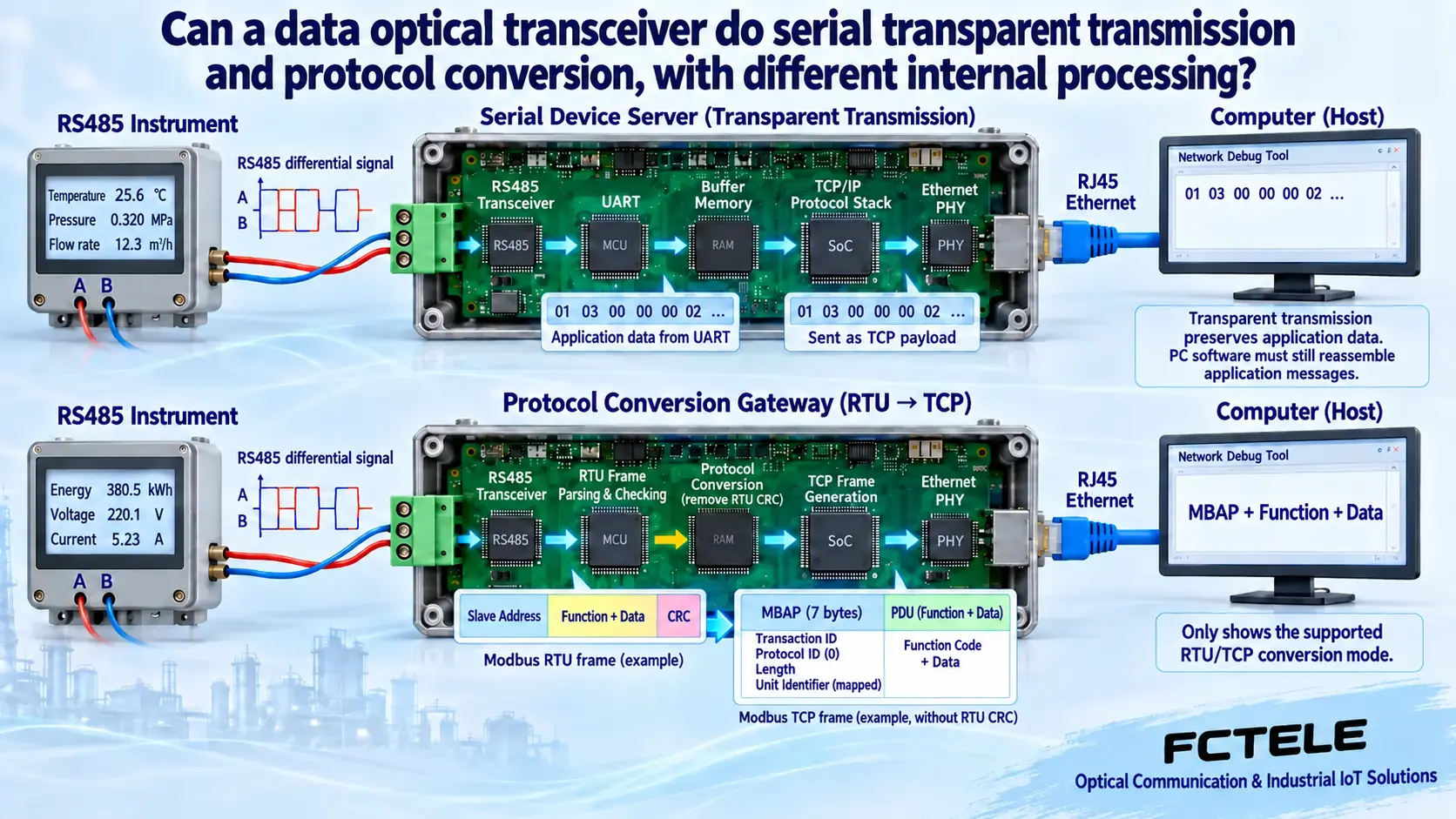
The electrical front end receives signals, the UART recovers bytes according to the character format, and the buffer and network protocol stack send them to remote software. Transparent mode usually preserves the application bytes, and the computer continues to request and parse according to the instrument protocol. The buffer is limited. A TCP connection being online does not mean the serial port has responded, and even less does it mean the instrument value is valid.
TCP transmits an ordered byte stream. One application read may obtain only part of a message, or may contain multiple messages. Reassembly should be based on length, delimiters, or protocol rules. A network packet or a single read must not be treated as a complete serial frame. Multiple acquisition programs sharing half-duplex traffic also require access coordination.
A protocol gateway must parse encapsulation, routing, and transactions
When Modbus RTU/TCP is explicitly supported, the gateway must handle the network MBAP header, serial station number, and CRC, and correctly match requests with responses. Business content such as function codes and data can be preserved, but the complete message is not passed through unchanged. Which types of address mapping, exceptions, and concurrency are supported should be checked according to the product version.
After parsing the encapsulation, the data must still be interpreted: register locations, signed or unsigned, word order, scaling, units, and invalid states require a point table. One device’s value multiplied by 0.1 gives temperature, but that does not mean all devices convert this way. The fact that a gateway can convert one protocol combination does not mean it will automatically recognize all proprietary commands.
4–20mA sampling has an independent measurement front end
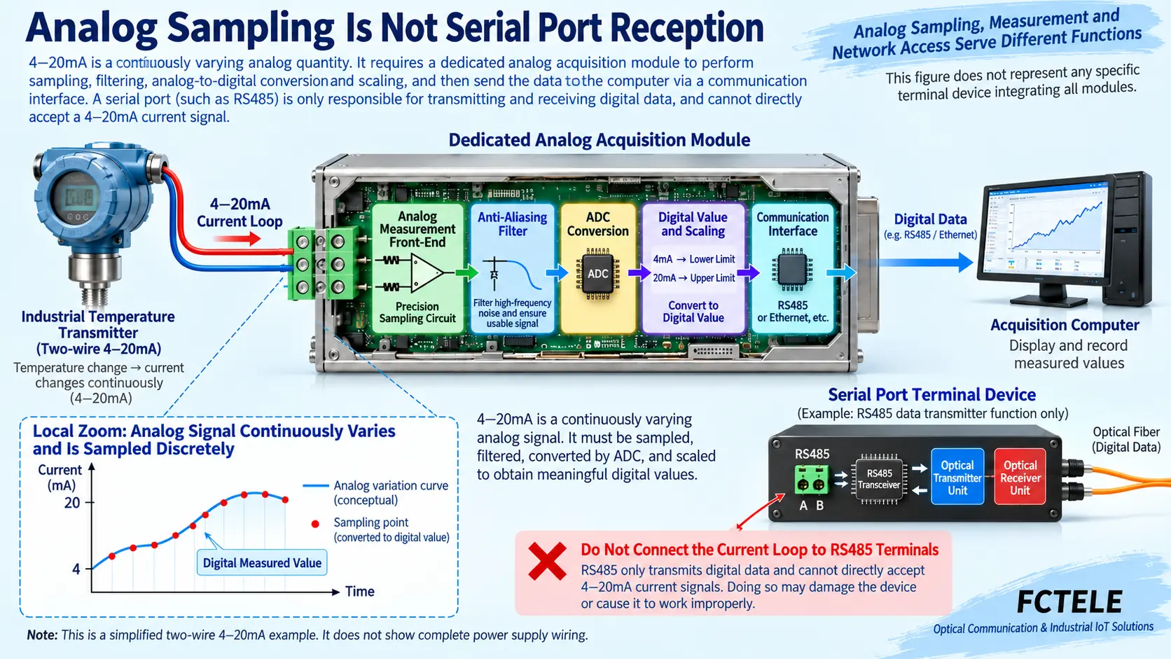
A current loop carries a continuous analog quantity. A suitable measurement front end first converts it into a measurable condition such as voltage, then obtains discrete digital values through filtering and analog-to-digital conversion, and then converts according to the range. ADC means analog-to-digital conversion circuit. An ordinary RS485 transceiver judges digital line states; it is not a current measurement front end.
A current loop cannot be connected to RS485 terminals for trial use; first check active or passive input, power supply, loop load, polarity, and isolation. A two-wire loop also requires complete power supply conditions. The simplified path in the teaching diagram cannot replace construction wiring. Miswiring may damage equipment and cannot be solved by changing the baud rate.
Analog extension and digital acquisition have different acceptance goals
Some analog optical devices reconstruct the corresponding current or voltage output at the remote end. Acceptance looks at the input-output relationship, range, and error; a digital acquisition module hands the measurement result to a communication interface, and digital encoding and application reading must also be considered. Having an internal ADC does not prove that the device definitely integrates Ethernet or a protocol gateway.
HART has digital communication in compatible loops. Whether ordinary analog transmission preserves it requires clear evidence. CAN, Profibus, and others also each have their own physical and protocol conditions and cannot all be classified as ordinary serial ports and then connected with the same type of optical modem. Changing the medium to fiber will not cancel the requirements of the original service.
How to use the integrated functions of the FCT-1500 for selection
The Feichang 2855 details correspond to the FCT-1500 series, listing combinations of RS232/422/485, electrical ports, and optical ports, and clearly specifying virtual serial ports, RTU/TCP conversion, and designated network modes. This shows that the corresponding configuration can combine serial access and network processing. It cannot prove that all optical transceivers can sample analog quantities or translate arbitrary protocols.
When ordering, check the number of channels, interface standard, operating mode, firmware, point table, and access method. Also confirm whether the optical port carries a network uplink or dedicated transmission. Do not connect another serial optical modem just because the same type of module can be inserted. Product options and factory configuration should be implemented according to the current delivery documents.
First use one terminal to prove that each step is not confused
Suppose an RS485 temperature instrument is to be read by control room software. First use a short cable to confirm a legal request and a real response, then choose either optical extension of the original serial service or network access. If protocol conversion is required, write down the source protocol, target protocol, station number, and registers. The requirement must not be reduced to one sentence: data to optical.
Use a read-only task to verify the complete message, device display, host value, and units, then expand nodes and load. If the source end does not respond, check wiring and character conditions. If the network cannot connect, check the address and role. If the bytes are normal but the result is wrong, check the protocol and point table. Keep evidence separately for each layer, and do not change multiple variables at the same time.
Continuous acquisition also needs to know when values become invalid
Record normal response time, timeout, checksum errors, reconnection, and power recovery, and indicate the last valid sampling time. After the source end goes offline, old values must not continue to be treated as new data; control tasks must also separately verify action feedback and the risk of repeated retries. Acquiring one number is only the beginning of acceptance, not the end.
Delivery includes ports and lines, power supply, range, character format, protocol, mapping, permissions, and configuration backup. If maintainers can trace from the physical input all the way to the final value, they can distinguish what optical transmission, electrical adaptation, digital networking, and actual sampling each completed.
Documentation note: The illustrations are general mechanism diagrams and have been technically checked; appearances marked with model numbers refer to official website photos, and other cutaways and components do not represent the actual internal circuits of Feichang Technology products. They are not measured waveforms or real project sites. Wiring and power supply are subject to the delivery manual.
Verification materials: Feichang Technology FCT-1500 serial server
Modbus official TCP encapsulation and transaction guide
TI RS485 design guide
Translated from the Chinese technical article. Source first published: 2023-11-22. Source last revised: 2026-10-13. Read the Chinese source
