


Before installation, draw the direction of every interface
To commission an HDMI optical transceiver, first prepare a connection diagram that lets you find each cable by following the drawing: the source device’s HDMI OUT connects to the transmitter’s HDMI IN; the transmitter and its matching receiver connect by fiber according to the instructions; the receiver’s HDMI OUT connects to the display’s HDMI IN. The source can be a computer or a player, and the display end can be a screen or a projector. The formats actually supported are still determined by the whole combination.
Label the devices at both ends, the fiber cores and the cables with names and numbers, and record the model, firmware, ordered optical ports and power specifications. For bidirectional video or multi-service products, the direction of each port must be written out port by port. You must not treat a monitoring loop-out as an input, and you must not mix up network transceivers just because the optical ports have the same shape. The generic link in this installation article is used to explain the steps; terminal wiring and interface functions are still subject to the manual for the exact model.
First arrange power, the optical path and maintenance space
At both ends, check separately the power, voltage and polarity required by the nameplate, and arrange grounding, protection, fixing and heat dissipation according to the equipment and site rules. The remote screen still needs its own power supply; fiber cannot carry copper-port PoE power across. Do not treat optional power versions as if one device can accept every power supply, and even more, do not mistakenly connect a serial port or alarm terminal to a power supply.
Confirm single-mode or multimode, available fiber cores, connectors, matched optical modules and wavelength conditions, and leave maintenance space to avoid pulling on connectors and bending too tightly. Received power has upper and lower limits, and even a short patch cord needs a suitable module. Use suitable tools for end-face inspection and cleaning, and handle it after confirming the working conditions; never look directly into an optical port or a fiber core that may be operating, and do not casually wipe precision end faces with ordinary cotton.
Step 1: Make the local direct connection a known-good baseline
For now, do not add the optical equipment. Use a known-good short HDMI cable to connect the source device directly to the display. Check the resolution, refresh rate, chroma, bit depth and audio that the project actually requires, rather than passing just because you see a boot logo. Save the system output settings, display identification information and test content; if even the direct connection is not normal, deal with the source, display or near-end cable first.
If protected content of the relevant kind needs to be played, the local combination must also be able to complete the required authentication normally. First verify a known test signal that is allowed to play, then verify the actual service. This can reduce mixing different problems together. After recording the local direct-connection result, try to keep the same source, same display, same short cable and mode for each later step, and add only one new condition at a time.
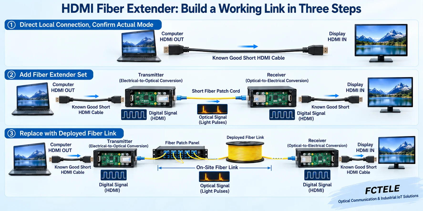
Step 2: Add the matching equipment and a suitable short fiber
Connect the transmitter and receiver according to the manual, use a short patch cord with suitable optical conditions, and power both ends correctly. The HDMI digital electrical signal is converted by processing supported at the transmitter end into an optical signal, and the receiver end restores the corresponding output; it is not a converter that automatically turns unsupported formats into supported ones. Check the indicator light meanings for the current model, and distinguish power, optical connection and video status.
Keep testing picture and sound in the local baseline mode, then verify the other required modes one by one under clearly supported conditions. If the short link fails, first check equipment matching, input/output direction, format, display negotiation and power, rather than rushing to tear apart the on-site optical cable. For models that need no settings, do not search for a gain menu out of thin air; you also should not adjust transmit power or a distance switch by following instructions for another type of equipment.
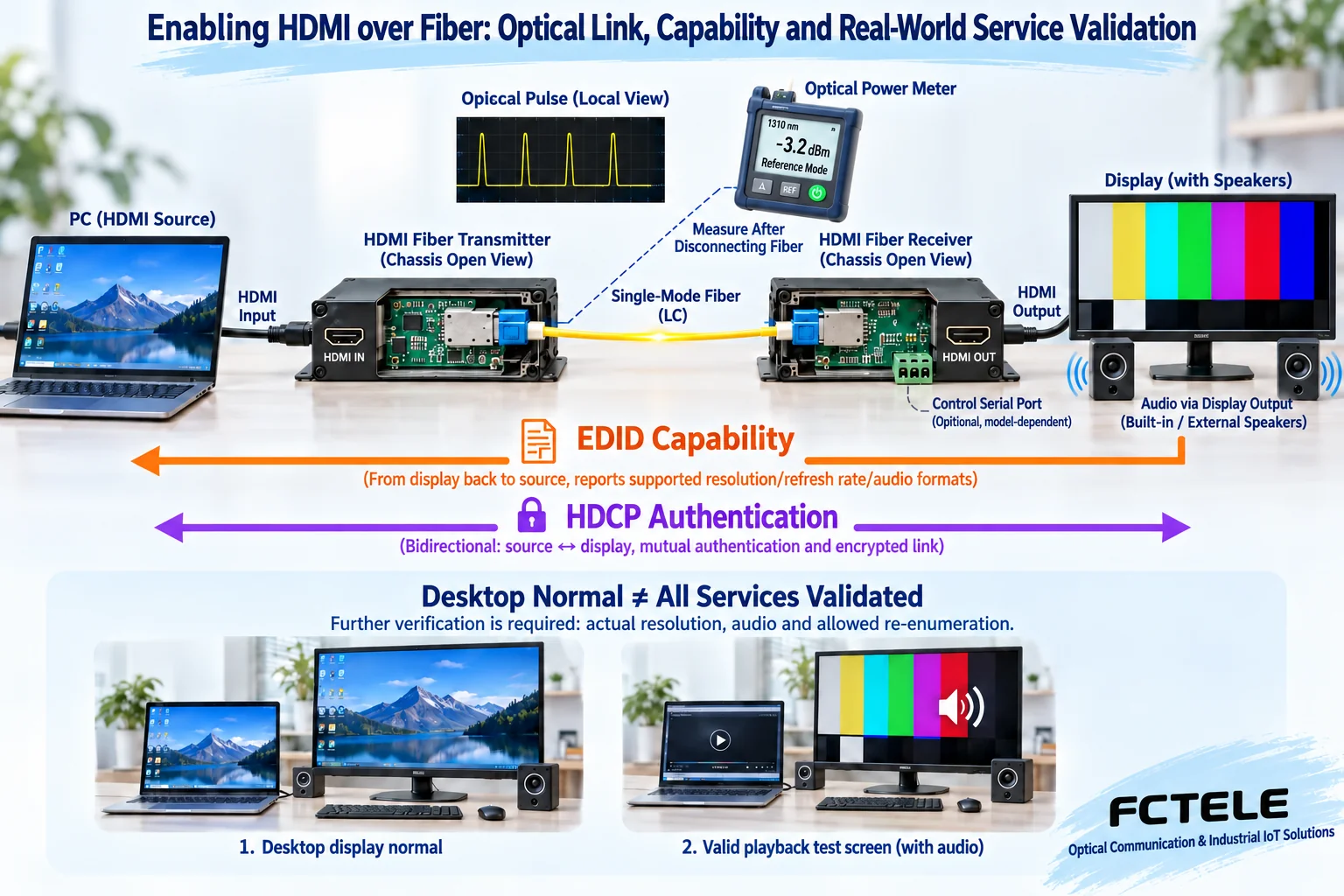
Step 3: Replace only the short patch cord with the live optical path
After the short link is stable, keep the equipment and settings at both ends unchanged, and connect the confirmed numbered live fiber core. This step mainly adds the on-site optical cable, connectors and splice points, which can help distinguish equipment combination factors from optical path factors. Check the transmit and receive relationship and the loss of the whole line according to the conditions of the selected optical module, and record the measurement tool, wavelength setting, location and reading.
An ordinary optical power meter usually needs the corresponding optical path to be disconnected for measurement, so it should be operated within an allowed maintenance window. You must not understand the independent test illustration as online monitoring without interrupting service. Compare the received reading with the module’s allowed window; both too weak and too strong need to be checked. If further locating of loss is needed, personnel with the proper conditions should use a test method suitable for the line, and should not use an indicator light being on as a substitute for optical path measurement.
Confirm display capability and content authentication separately
EDID describes the display’s supported capabilities, and the source device chooses its output based on it; an extender may pass it back, cache it or provide preset data. Record the strategy used according to the model, and when changing displays, check again whether old capability information is still retained. Reading EDID does not prove that the high-speed video main path is necessarily stable, and an optical path being connected does not prove that the display accepts the source’s current settings.
HDCP handles link authentication for the corresponding protected content, and is different from EDID. When the desktop is normal but the actual program is black, keep the conditions under which it occurs and check the supported combination of source, extender and display. Feichang FCM-H1-4k2 documentation lists EDID passback and corresponding HDCP support items, but final commissioning still requires actual equipment and service verification. These items must not be understood as unlimited compatibility with all content and all displays.
Test audio, control and peripherals separately
If there is picture but no sound, first check whether the source is sending audio to HDMI, whether the display end has the corresponding playback capability, and which audio formats the equipment supports. Independent analog audio, microphone and HDMI embedded audio may be different paths, and you cannot conclude that the sound problem is solved just by changing the fiber. If multi-service equipment is used, list the source, destination and direction of each channel in a table.
Serial control needs matching electrical interfaces, pins and communication parameters, and an extension channel does not automatically translate display commands. Successful USB keyboard and mouse operation does not mean a camera or all touch devices are supported. Feichang FCM-H1dG1U1 lists related auxiliary interfaces, and the actual peripheral category, direction and concurrent combination need separate checking; when a conference camera is needed, host enumeration and actual capture performance should be checked independently.
Acceptance covers real use and allowed recovery operations
Let the actual modes, dynamic picture, sound and planned auxiliary services run together, and cover the continuous operating conditions agreed for the project. Test source restart, display restart and equipment power recovery separately in allowed ways, and record whether negotiation, display and control can be re-established. So-called uncompressed or visually zero-latency cannot replace testing the complete system response and recovery performance.
When flickering, black screen or abnormal color occurs, first save the mode, power, equipment status and operation sequence at that time, then change only one item at a time for segmented checking. Do not judge an HDMI problem by expecting snow after unplugging the fiber as with analog video. For detailed fault locating, you can combine the HDMI black screen and flicker topic in this technology center; for installation acceptance, you should keep the normal baseline and live optical path tests, and avoid mixing the two types of tasks into blind parts replacement.
Let the next maintenance person reproduce the result
The acceptance record includes model and firmware, interface direction, fiber core number, power location, optical pairing, complete video mode, EDID strategy, service verification and recovery results. The original wiring diagram, actual settings and abnormal records should correspond to the same set of equipment. In the future, when changing screens, adding USB peripherals or raising video specifications, maintenance personnel can use this to know which conditions need to be rechecked.
The core of this commissioning method is to build evidence step by step: direct connection proves the source and display end, the short optical link proves the matching equipment, the live optical path checks on-site transmission, and then negotiation, authentication and actual services are verified separately. The success of each step can only prove the conditions it covers, and cannot be expanded to mean that all modes are supported. Installing in this order allows troubleshooting and acceptance to produce reviewable results.
Documentation note: The principle diagrams have been checked for technical content and are used to explain generic mechanisms; they are not physical product photos or measured records. Specific interfaces, modes and capabilities are subject to the selected model, version and on-site verification.
Verification materials: Feichang FCM-H1-4k2 HDMI product documentation
Feichang FCM-H1dG1U1 multi-service product documentation
Extron HDMI fiber extender user manual
Related technical topics: What is an HDMI optical transceiver: electrical-to-optical conversion, display negotiation and transmission boundaries How to choose an HDMI optical transceiver: complete video modes, optical path budget and auxiliary interfaces HDMI black screen and flicker troubleshooting Conference room display and USB, IP service planning
Translated from the Chinese technical article. Source first published: 2024-04-18. Source last revised: 2026-10-13T12:13:11+08:00. Read the Chinese source
