


First, clarify the connection you want to extend
When a computer is in an equipment room and a large screen is in another building, and a standard HDMI cable is not suitable for running directly across the entire route, a matching HDMI optical transceiver can be considered. A typical combination is a transmitter, fiber, and receiver: the computer connects to the transmitter’s HDMI input, and the receiver’s HDMI output connects to the screen. It extends an explicitly supported audio-video connection, and the screen still receives an HDMI signal in the corresponding format.
HDMI is High-Definition Multimedia Interface, which can transmit digital video and corresponding audio. The optical transceiver handles the conversion between electrical and optical signals for one segment and processes auxiliary functions specified by the model. It is not a device that automatically turns ordinary images into high-definition images, nor is it a router that connects a computer to the internet. Before purchasing, clearly write down the source device, display device, target video mode, and distance; this is more accurate than just saying you need a pair of high-definition devices.
The input is already a digital signal, so there is no need to capture the image again
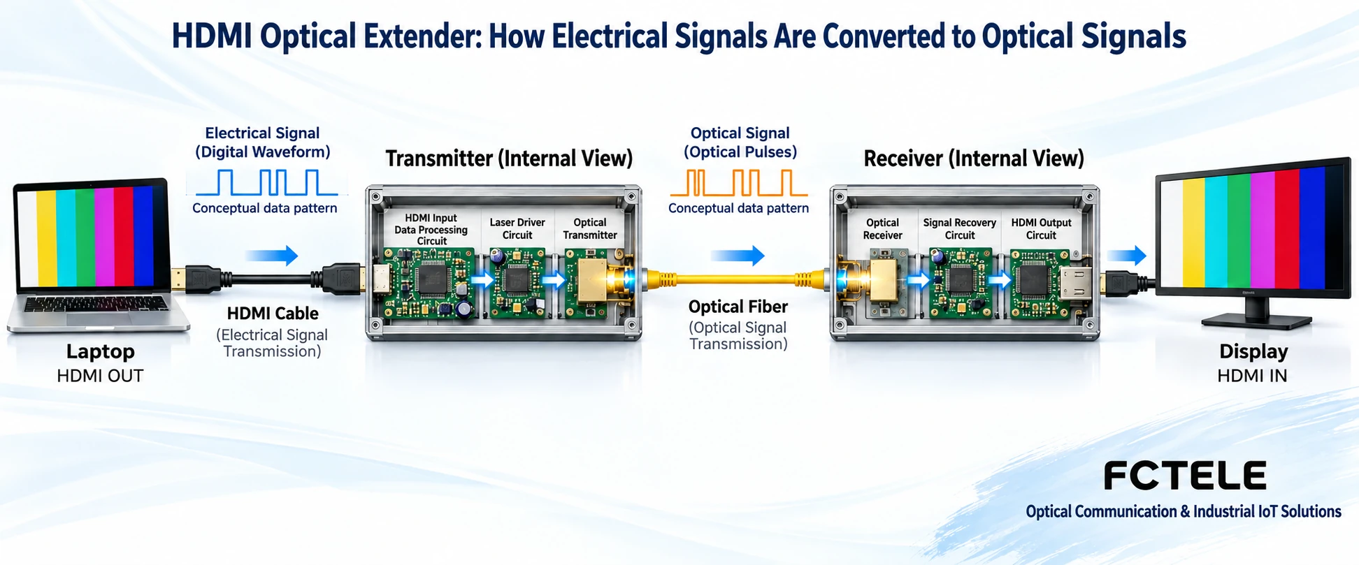
The computer has already organized the display content into a digital signal on the HDMI interface. The transmitter first takes these signals, then arranges, encodes, or organizes transmission channels according to its own structure, driving the optical transmitter to produce an optical output that changes with the data. The fiber carries this variation to the far end, where a photodetector in the receiver converts it back to an electrical signal; subsequent circuits recover the data and provide an HDMI output. Whether channels are aggregated and which line coding is used are determined by the product implementation.
The waveform in the figure is only to help understand that the same information can use different carriers; it is not an oscilloscope measurement result. The HDMI input should not be universally drawn as an analog-to-digital converter sampling an analog image; that belongs to another type of signal processing task. Common earlier HDMI interfaces use TMDS transmission; TMDS is a digital signal encoding and transmission mechanism, and newer interface mechanisms differ. You cannot infer from the HDMI label on the casing that all devices have identical internal circuits.
Fiber improves the intermediate transmission conditions, but capability is still determined by the entire link
Fiber is suitable for extending distance under clear optical conditions. The fiber core does not rely on metal conductors to carry this video signal, which also helps reduce electromagnetic coupling issues in that segment. However, the power supplies at both ends, HDMI copper cables, connectors, and electronic devices still have their own operating conditions. If the source already outputs the wrong format, or the near-end HDMI cable cannot stably transmit high-speed data, switching to a longer fiber will not fix it.
Optical transmission also has loss. Fiber type, connectors, splice points, optical module pairing, and received power window all need to be checked; fiber cannot be described as having no attenuation. The same optical port shape only proves that the mechanical interface may be similar, not that the internal services and coding are compatible. Ethernet transceivers, SDI optical devices, and HDMI receivers each have different targets; they cannot be interchanged just because they can all be plugged into fiber.
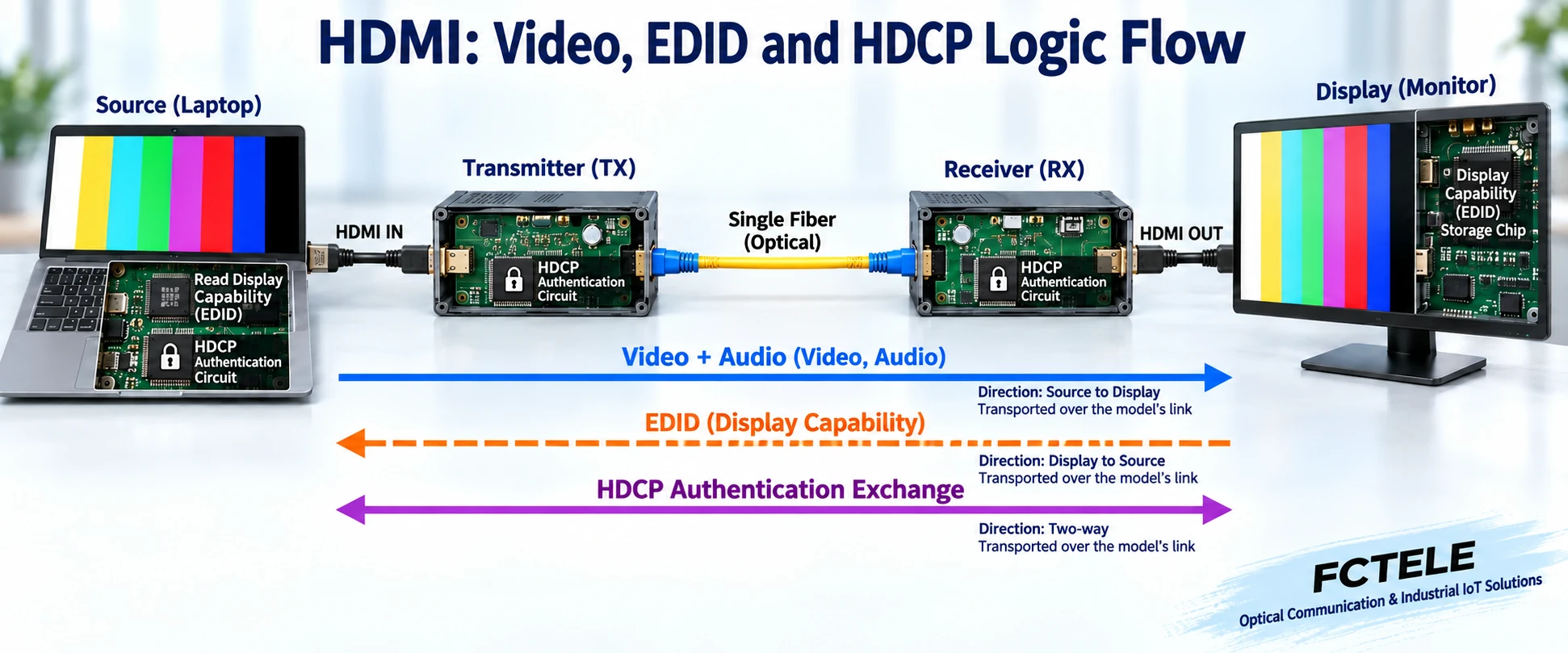
How the display tells the computer what it can display
EDID can be understood as a capability description provided by the display device, including corresponding display modes and audio information. After the source device reads this information, it decides the output mode based on its own settings. The image is mainly sent from the computer to the screen, while display capabilities need to return from the screen side to the source; the two logical directions are different, which does not mean a separate fiber must be run on site. How the extender transmits control information depends on the specific model.
Some devices forward EDID in real time, while others can store, learn, or provide preset capabilities. If old information is still used after changing screens, the source may select a mode that the new screen cannot accept. Therefore, plug-and-play also requires the entire combination to negotiate correctly. Models without learning or configuration functions should not be expected to have menus, and data from unknown sources should not be written arbitrarily; first record the actual mode and the handling method in the device documentation.
HDCP and EDID are not the same thing
HDCP corresponds to link authentication for protected digital content, while EDID describes display capabilities. The desktop being able to display does not mean a certain protected program can definitely play; establishing an optical link also does not mean authentication compatibility is complete. The source, extender, and display end need to meet their respective support conditions. The bidirectional arrows in the figure express authentication interaction and do not mean all devices have bidirectional video transmission.
During troubleshooting, you can use a known signal that is allowed to play to distinguish between a general video path and authentication issues with actual content. Ultimately, you still need to verify the content and device combination actually used in the project. The goal is to make the declared supported link work normally, not to bypass content protection by changing fiber, turning off unknown options, or adding adapters. For functions not explicitly stated by the product, confirm with the manufacturer; do not infer from a similar series name.
Uncompressed, lossless, and latency need to be explained separately
Uncompressed usually means the device does not use corresponding video compression encoding to reduce data volume, but it may still organize transmission data, perform line coding, and recover timing. Lossless compression is another implementation method; these two terms cannot be treated as synonyms. If the device changes chroma, bit depth, or output mode, these conditions must also be clarified; only seeing an image at the receiver does not prove that input and output are completely identical in every item.
Even without lossy video compression, light propagation, circuit processing, and the display itself take time. The promotional term visual zero latency is not suitable to be rewritten as absolutely no delay physically; what affects interactive experience is the end-to-end performance of the complete system. When there are console, touch, or synchronization requirements, test the response along the actual path; the speed of a single optical component cannot replace the result of the entire system.
Use Feichang Technology product information for verification, not pieced-together parameters
The Feichang Technology FCM-H1-4k2 details list supported items such as HDMI 2.0, 4K 60Hz, and EDID return, which can be used to verify single-channel display extension requirements. Another model, FCM-H1dG1U1, is aimed at bidirectional HDMI and multi-service combinations. Although both use HDMI and fiber, their input/output conditions and additional interfaces are not the same; the exact model and ordering version should be checked separately.
For example, if a USB camera is needed, you cannot assume any camera will work just because there is a USB socket; you also need to confirm the device class, USB speed, power supply, and simultaneous operating conditions. If RS232 control is needed, the serial path will not automatically understand the screen control protocol. If website fields have different descriptions, ask the manufacturer to confirm the actual delivery mode in writing to avoid combining the highest capabilities from different pages into a product that does not exist.
Use a simple test to turn the principle into an acceptable connection
First, have the computer connect directly to the screen with a known-good short HDMI cable, and save the target mode and audio output settings. Then add the matching optical transceiver and suitable short patch fiber, and check whether the same mode can work continuously. Finally, keep the devices and settings at both ends unchanged, and replace only the middle with the installed optical path. This can distinguish problems with the local interface, the transmission device combination, and the on-site fiber cable, avoiding the inability to explain the cause after changing multiple items at once.
Acceptance covers the actual resolution, refresh rate, color format, audio, and allowed recovery operations; required auxiliary channels are also tested separately. Record the model, firmware, fiber core number, power supply, negotiation strategy, and test results. After understanding this path, readers should be able to explain: an optical transceiver extends an HDMI connection under supported conditions; electrical-to-optical conversion, display negotiation, and content authentication each have their own tasks; and fiber itself will not automatically improve image quality or eliminate all compatibility limitations.
Documentation note: The principle diagrams have been checked against technical content and are used to explain general mechanisms; they are not product photos or measurement records. Specific interfaces, modes, and capabilities are subject to the selected model, version, and on-site verification.
Verification materials: Feichang Technology FCM-H1-4k2 HDMI product information
Feichang Technology FCM-H1dG1U1 multi-service product information
TI TDP0604 HDMI 2.0 electrical interface and DDC, HPD information
Extron HDMI fiber extender user manual
Related technical topics: How to choose an HDMI optical transceiver: complete video modes, optical budget, and auxiliary interfaces How to install and debug an HDMI optical transceiver: short-link pair test, optical path connection, and acceptance Troubleshooting HDMI black screen and flickering Conference room display and USB, IP service planning
Translated from the Chinese technical article. Source first published: 2019-10-25. Source last revised: 2026-10-13T12:13:11+08:00. Read the Chinese source
