


SDI optical transceivers and VGA optical transceivers may both use fiber, but the input signals they face are different. SDI usually connects to a serial digital video interface, while VGA connects to analog RGB images and synchronization. Similar optical ports do not prove that the two are interchangeable; when choosing, first look at the actual interface of the signal source, then check the video format and the receiving-end device, rather than just comparing the word “high definition.”
1. Identify the Signal from the Actual Interface
Common SDI devices use BNC connectors and corresponding video coaxial lines. The source end may be a camera or professional video device with SDI output. VGA commonly uses a three-row fifteen-pin interface, and the source end is mostly a computer or control terminal. BNC may also be used for analog video or other signals, so you also need to look at the port silkscreen and manual; the fifteen-pin shape also does not replace confirmation of input and output direction. Ordinary network cameras, analog surveillance cameras, and SDI cameras cannot be treated as the same input object.
2. SDI Is Already a Digital Serial Signal
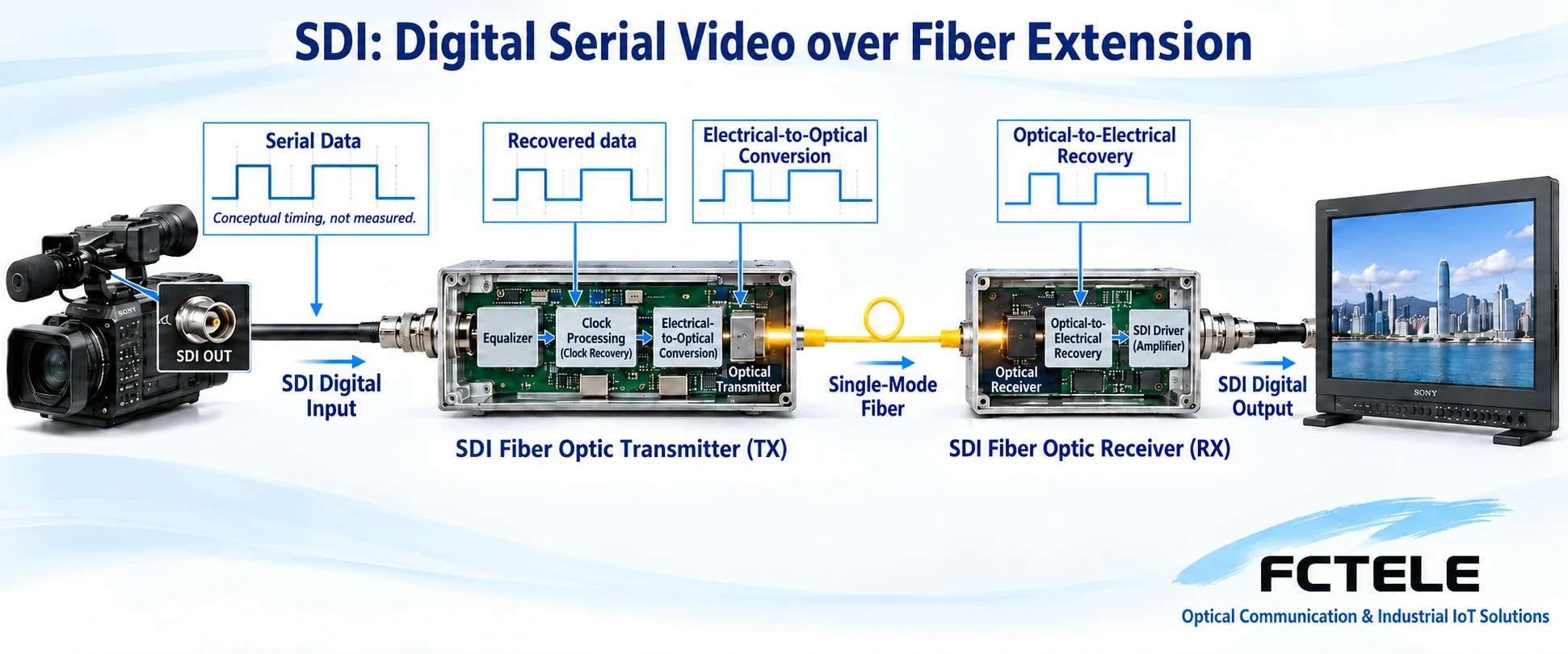
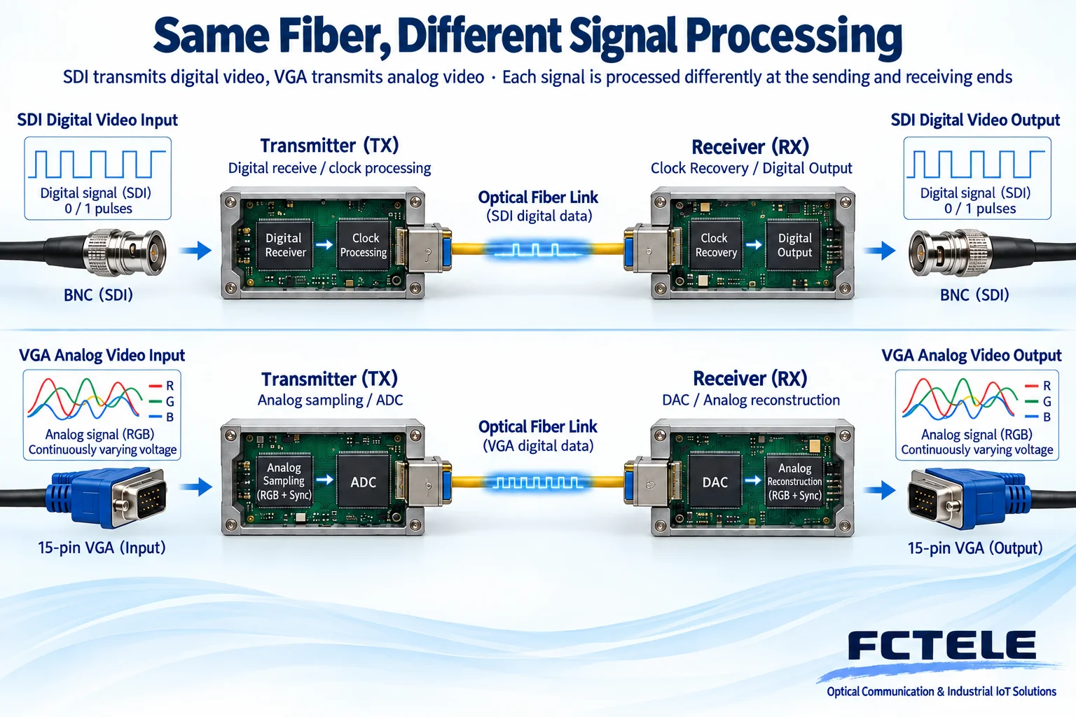
SDI organizes digital video into a high-speed serial signal according to a specified order. A typical fiber extension device completes reception, necessary equalization or clock processing at the input end, then performs electrical-to-optical conversion; the receiving end restores the corresponding serial electrical signal. The interface rate is related to the video format. For example, public SDI receiver materials distinguish operating grades of about 1.5 and about 3 gigabits per second, but this cannot be used to infer that all optical transceivers support all grades. In engineering, you also need to check the specific standard, mapping method, and additional data processing.
3. VGA Needs to Handle Analog Sampling and Synchronization
The colors of an analog RGB image are expressed by voltage, and the device also needs to recognize line and frame synchronization. A common digital VGA optical transceiver first samples to obtain color values, then transmits them over the optical link, and the receiving end reconstructs the analog output. Input bandwidth, sampling phase, supported timing, and analog cables all affect fine text and edges. The SDI source end is already digitized, while VGA equipment has to face the analog input stage, so the troubleshooting focus of the two types of products cannot be copied directly, even if they both ultimately transmit digital data inside the fiber.
4. Optical Transmission Does Not Equal Video Compression
The SDI interface itself does not mean that H.264 compression is used. Transparent SDI fiber extension and encoding video before connecting to a network are different solutions; the latter also requires encoding, decoding, and network stages. Therefore, uncompressed interface extension and compressed encoding into a network should be evaluated as two different paths. Whether a VGA optical transceiver compresses should also be checked in the design materials, and digitization should not be treated as a synonym for compression. Propagation, interface processing, and display all take time, so “zero latency” should not be used to summarize all devices and the entire system.
5. Optical Transceivers Cannot Automatically Complete Interface Conversion
When a computer only has VGA output but the endpoint only accepts SDI, an explicit format conversion link is needed; an SDI source connected to an HDMI monitor also needs a corresponding conversion device. A converter not only changes the plug, but also handles timing, pixel organization, and interface protocols. Some multi-interface products support specific conversions, but this must be verified according to the specific configuration, and non-existent capabilities cannot be added to a pair of single-interface optical transceivers. Similarly, an Ethernet optical module in a network switch cannot undertake any SDI or VGA link just because the interface can be plugged in.
6. Do Not Assume Audio and Control Are the Same
Some SDI systems support embedded audio and additional data, but whether the device transparently preserves this content still needs to be confirmed. The VGA interface itself does not carry audio. When there is a need for sound or keyboard and mouse, a corresponding channel usually has to be set up separately. Control return, camera control, and KVM are different services, and their protocols, directions, and permissions should be explained separately. Successful video display at the remote end does not prove that control return is also successful. You cannot accept only the main picture and omit the other channels required by the project.
7. A Hypothetical Example of Choosing the Wrong Interface
Assume that the camera port at the site is clearly marked SDI, and the duty room still keeps a monitor with VGA input. Buying only a VGA optical transceiver cannot turn the camera output into an analog computer signal. You can first choose an SDI extension link that matches the source-end format, then verify whether the terminal conversion device supports the target display mode; the architecture may also be adjusted according to the on-site equipment. This does not prescribe a single procurement combination, but requires that the input and output at each step correspond continuously, to avoid leaving interface conversion out of the budget.
8. How to Distinguish Acceptance and Fault Location
For the SDI path, first check the source-end format, input lock, coaxial cable quality, device-supported grades, and optical path; for the VGA path, add direct-connection image quality, color contacts, sampling, and display timing comparison. Both should first undergo a short-distance paired test, then be connected to the on-site fiber cable, recording loss, connectors, and abnormal times. Indicator light status only explains part of the states defined by the device. In the end, you should also check the complete video, audio, and additional services. Do not look directly into the optical port, and do not repeatedly test by connecting unknown signals to mismatched ports.
9. Sources and Feichang Technology Product Boundaries
The Feichang Technology official website has separate SDI and VGA categories, providing entry points for searching by interface. This article uses public chip materials to explain general mechanisms and does not prove that specific Feichang Technology products use those chips. Specific distance, control capability, and suitability for high-magnetic-field medical environments all require evidence for the corresponding model and cannot be determined based on category names. Special computer room audio and video solutions are covered in separate articles. Compliance conditions for MRI environments must be confirmed separately and cannot be directly inferred from fiber transmission.
You should also distinguish input cable equalization from optical path loss handling. The former improves the electrical signal conditions received by the device, while the latter determines whether the received optical power meets the operating range. The two cannot replace each other. If the SDI source format changes, the optical path may be normal but locking may still fail because the device does not support the new format; if the VGA output mode changes, the analog interface may be normal but the screen may be black because the supported timing does not match. Saving the source-end mode and short-cable test results can avoid misjudging a compatibility problem as a broken fiber. Cross-brand pairing requires evidence of interoperability and cannot be concluded solely from the same interface and nominal rate.
Sources:Semtech: SDI receivers and rate grades;Analog Devices: RGB graphics sampling and synchronization clock materials;Feichang Technology: VGA optical transceiver category entry. The illustrations explain general mechanisms; they are not product photos, measured waveforms, or certification documents.
Related topics:VGA optical transceiver working principle;VGA selection checklist;VGA installation troubleshooting;Classroom meeting planning;HDMI and VGA interfaces;VGA to HDMI and image quality;Special equipment room solutions
Translated from the Chinese technical article. Source first published: 2022-06-29. Source last revised: 2026-10-13T12:28:34+08:00. Read the Chinese source
