


Evaluating the energy consumption of an SDI optical transceiver should start with the actual power supply and where the heat goes. The maximum output power on the adapter is not the power the device consumes every day, and a warm enclosure alone cannot prove a fault. You need to measure actual operating conditions, then judge together with power supply efficiency, environment, heat dissipation, and service arrangements. An ordinary optical transceiver should not be assumed to have automatic sleep, port power saving, or smart fan functions.
1. What the adapter rating means
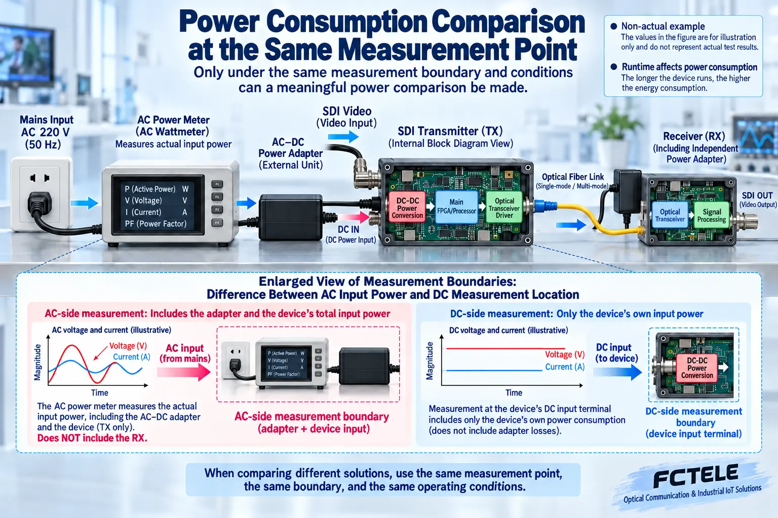
The voltage and maximum current marked on the adapter are usually used to describe what it can supply to the device. For example, a rating of 5V, 1A corresponds to a maximum rated output of 5W, but it does not mean the device always draws 5W. The actual power consumption of the device is affected by design and operating state, and the adapter also has conversion loss on the AC side. When measuring, you must clearly distinguish whether you are measuring at the adapter input or at the device DC input, and you cannot mix the two kinds of data in the same comparison table.
The device voltage, polarity, and connector should be checked according to the model. You must not arbitrarily lower the voltage to reduce power consumption, and you must not force power with a higher voltage. Whether an adapter with a larger rated current can be used still must meet voltage, polarity, connector, and quality requirements, rather than simply assuming that a larger current is more dangerous or more energy-saving. Poor cable contact or voltage drop can also cause abnormal operation, and energy-saving analysis cannot be separated from reliable power supply.
2. Why the device generates heat
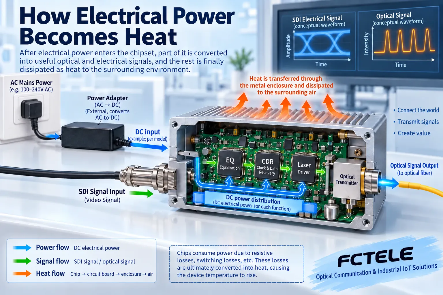
Input signal processing, clock circuits, line drivers, and optical transceivers all use electrical energy, and part of that energy is eventually converted into heat. The chip transfers heat to the circuit board, thermal conduction structure, and enclosure, and then sends it to the surrounding air through convection and radiation. A warm enclosure may reflect that it is conducting internal heat, but human touch cannot replace the judgment of allowable temperature, nor can it prove that the internal chip is necessarily in a safe condition.
The same device may have different temperatures on a desktop with air circulation and in a stacked, closed cabinet. Heat from other equipment in the cabinet, installation gaps, ambient temperature, and airflow all affect the result. Ventilation holes blocked by cables, or multiple small boxes placed tightly against each other, may make it difficult for heat to leave. Do not disassemble the enclosure without authorization, add an unmatched fan, or modify the circuit. Give priority to improving the environment according to the installation requirements in the manual.
3. How to measure power consumption so it is meaningful for comparison
Use measuring equipment suitable for the range and power supply type, and record the measurement point, input voltage, operating mode, device configuration, and test time. On the AC side, pay attention to actual active power; you cannot casually treat apparent power, voltage multiplied by current, as real power consumption. When measuring the device DC input, you can estimate input power by combining voltage and current readings, but you must confirm that the readings are stable and the instrument accuracy is adequate, and you must not treat an instantaneous peak as an all-day average.
If comparing two devices, test them under the same service requirements: the same SDI rate, number of channels, optical configuration, and environment. A single-channel small box and a rack device with multiple auxiliary channels cannot be directly evaluated for efficiency only by total wattage. You should look at whether it can meet the requirements, and also at how much electrical energy the transmit and receive devices, adapters, and additional converters of each system use in total, so as to avoid omitting the power consumption of supporting devices.
4. How to calculate operating electricity
Average active power multiplied by operating time can estimate electricity. For example, if a system actually consumes an average of 8W and runs for 24 hours, the estimate is 0.192kWh; this is a calculation example, not a measured value of a Feichang model. If it only runs for part of the day, calculate according to the actual arrangement, and state whether adapters and supporting equipment are included. Electricity price and usage hours should use the project’s own data, and do not fabricate general cost-saving amounts.
Broadcast, security, or remote monitoring that runs continuously cannot be casually shut down to save power. When shutdown arrangements are needed, first confirm which services depend on that link, whether recording is needed, how to restart, and how to verify after recovery. If there is no model documentation clearly supporting automatic energy saving, do not add sleep and wake functions to the procurement table. Even if supported, it is necessary to verify whether it is suitable for usage scenarios requiring continuous images.
5. Temperature rise measurement should fix conditions
Record ambient temperature, device operating time, and enclosure measurement point, and compare under conditions close to stable operation. Different surface materials and infrared temperature measurement settings affect readings. Follow the instructions when using tools, and use a suitable contact method when necessary. The measured enclosure temperature is not directly equal to the chip junction temperature; a single enclosure temperature value cannot replace thermal design verification or operating temperature certification of the whole product.
Temperature rise is the change relative to the environment. When comparing, record both the absolute temperature and environmental conditions. If abnormal intermittent operation and high temperature occur at the same time, first rule out power supply, cable, optical receive margin, and format issues, then check the environment and installation according to the manufacturer’s regulations. You cannot attribute all black screens to overheating, nor declare the temperature normal just because it is not hot to the touch. Recording the time relationship on site helps locate the problem, rather than drawing a conclusion from a single measurement.
6. How to select models using Feichang product information
The Feichang SDI product categories include different rates, channel counts, and installation forms. Choose according to need, and do not blindly configure large rack equipment for a single-channel service. The one-channel 3G and one-channel 12G pages provide their respective functions and power supply descriptions. During procurement, check the device input and adapter configuration of the actual ordered version; when different power options exist on the page, do not treat the AC-side adapter input voltage as the direct input of the small box device.
The final choice must simultaneously meet format, optical path, continuous operation environment, and maintenance conditions. Ask the supplier to provide the power supply requirements, allowable environment, and installation instructions for the selected configuration, then use a sample to verify actual power consumption and temperature rise. Only in this way can energy consumption be controlled without harming reliability; low-power advertising, a fanless appearance, or the parameters of a certain third-party chip are not enough to replace verification of the finished product under project conditions.
When multiple devices share power or a cabinet, check the total power supply capacity, actual cable voltage drop, and total cabinet heat load. The rating of a single adapter does not represent the stable operating capability of the entire cabinet. Before expansion, include the new devices within the same system boundary, and after meeting electrical and installation requirements, record power consumption and environment again, so as to avoid linearly inferring all results only by the number of devices.
Sources:Feichang one-channel 3G SDI optical transceiver;Feichang one-channel 12G SDI optical transceiver. The illustrations explain general mechanisms; they are not product photos, measured waveforms, or certification documents.
Related topics:How an SDI optical transceiver works: coaxial reception, clock processing, and optical-electrical conversion;How to understand SDI synchronization: differences between bit clock, line and frame markers, and studio synchronization;SDI optical transceiver signal processing: what equalization, clock recovery, and retiming each solve;How to test and accept an SDI optical transceiver: format, bit errors, optical power, and continuous operation;SDI optical transceiver installation and troubleshooting: short-cable baseline, optical-link commissioning, and segmented localization;How to choose between SDI monitoring and IP monitoring: transmission, recording, latency, and security boundaries;How to check no picture or no sound when converting SDI to HDMI: power supply, locking, and display compatibility
Translated from the Chinese technical article. Source first published: 2024-04-18. Source last revised: 2026-10-13T12:21:24+08:00. Read the Chinese source
